


Time Zone Identification in Browser Forensic Analysis
In a digital forensic examination, establishing which Time Zone the system had been set to should one of the first examination tasks. If this information is not established at an early stage and taken into account, the validity of Date/Time evidence may be brought into question. Not only is this true for the examination of Browser History and related artefacts, it is also important when examining file system metadata.
I also believe this is something every examiner should be able to do manually, as opposed to relying on point and click or script forensics. Whilst point and click certainly has a place and software tools can greatly increase the efficiency of the examination process, digital forensic practitioners need to possess the skills and ability to verify the results.
Some Date/Time values stored in binary files are affected by the Time Zone setting of the original suspect computer and many digital forensic applications can alter the representation of these dates by the Time Zone setting of the forensic workstation.
This becomes particularly complicated when the suspect computer was set to an incorrect Time Zone and the computer clock was set to correspond to the Local Time Zone. Many of the Date/Time stamps store the data as UTC values. In such circumstances, the Operating System (or application) has to convert the value from Local time to UTC.
Case Example
This was demonstrated in a case I was asked to review a number of years ago. A computer had been seized as part of an investigation into abusive images of children. The police had examined the computer correctly and the individual involved had been charged with offences under the Protection of Children Act 1978.
A defence expert examined the forensic image from the computer had declared in his report that the police had tampered with the evidence and alleged that they were responsible for the illegal material as the Date/Time stamps show the material was created on the disk some four hours after it had been seized by police.
My initial examination revealed that the defence expert had not established the Time Zone settings for the system nor had he taken them into account during his examination and subsequent report. If he had, he would have seen that the system was incorrectly set to Pacific Time and not GMT. As far as the Operating System was concerned, the system was in Pacific Time and added 8 hours to the Local times to convert them to UTC. This resulted in the Date/Time stamps being 8 hours in advance of the correct time.
When the defence expert stated the computer had illegal material written to the disk after the system was seized, it was in fact that this had happened some 4 hours prior to the warrant being executed at the home of the suspect.
Establishing the Current Time Zone
To establish the Time Zone setting for a Microsoft Windows system, the forensic examiner can examine the SYSTEM registry hive. To do this, you need to establish which ControlSet was active when the computer was seized.

Figure 1
There you will find 4 keys detailing the Current, Default, Failed and LastKnownGood control sets. The current control set in the screen below is set to 3. You can also see the there are three ControlSets numbered 001 to 003.
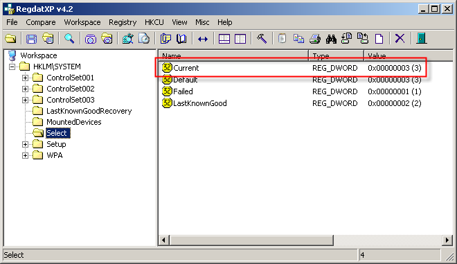
Figure 2
Now that this current control set has been identified, we can navigate to that location in the registry and calculate the different values as stored. In this case, the Time Zone settings are stored here:

Figure 3
The Time Zone Information for this Control Set is shown in Figure 4.
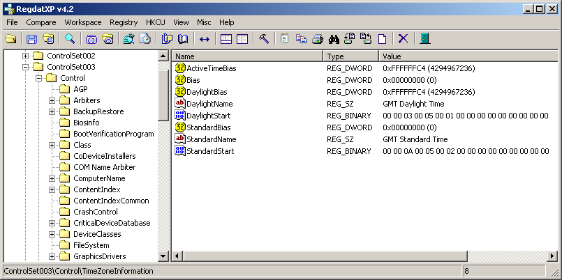
Figure 4
The keys are explained below. Please note that the bias settings are stored in minutes as a signed integer. The bias is the difference, in minutes, between UTC and local time. All translations between UTC and local time are based on the following formula:

Figure 5
ActiveTimeBias
This value is the current time difference from UTC in minutes, regardless of whether daylight saving is in effect or not. It is this value that helps establish the current Time Zone settings. Using the formula above, take this value and add it to local time to get the UTC value.
Bias
This value is the normal Time difference from UTC in minutes. This value is the number of minutes that would need to be added to a local time to return it to a UTC value. This value will identify the Master Time Zone (Standard Time).
StandardBias
This value is added to the value of the Bias member to form the bias used during standard time. In most time zones the value of this member is zero.
DaylightBias
This value specifies a bias value to be used during local time translations that occur during daylight time. This value is added to the value of the Bias member to form the bias used during daylight time. In most time zones the value of this member is –60.
DaylightName
The Operating System uses this name during daylight saving months to display the current time Zone setting.
DaylightStart
Binary data in SYSTEMTIME structure used to identify the date/time that Daylight Saving will commence in this time zone.
StandardName
The Operating System uses this name during daylight saving months to display the current time zone setting.
StandardStart
Binary data in SYSTEMTIME format used to identify the date/time that Standard Time will commence in this time zone.
DisableAutoDaylightTimeSet
This will only be visible if the setting to automatically adjust clock for daylight saving has been switched OFF.
Calculating Signed Integer Bias Values
Within digital systems, all data, whether they be numbers or characters are represented by strings of binary digits. A problem arises when you want to store negative numbers.
Over the years, hardware designers have developed three different schemes for representing negative numbers: sign and magnitude, ones complement, and twos complement. The most common method for storing negative numbers is twos complement. With this method, the Most Significant Bit (MSB) is used to store the sign.
If the MSB is set, then this represents a NEGATIVE number. This method affords natural arithmetic with no special rules. To represent a negative number in twos complement notation the process is simple:
• Decide upon the number of bits (n)
• Find the binary representation of the +ve value in n-bits
• Flip all the bits (change 1 to 0 and vice versa)
• Add 1
Figure 5 below shows the binary representation of the positive number 5.

Figure 5
To represent this as a negative number (using 8 bits) then the procedure above is followed. Flip the bits as shown above and add one as shown in Figure 6.

Figure 6
This method makes it extremely easy to add positive and negative numbers together. For example:

Figure 7
It also makes it extremely easy to convert between positive and negative numbers:

Figure 8
ActiveTimeBias
If we look once again at the ActiveTimeBias in Figure 9, you will see a signed hexadecimal value. This can be calculated using twos complement.

Figure 9
This value is stored in hexadecimal as a 32 bit value, so to work out the value it will need to be converted to binary. Ignore the fact that on this occasion, the registry editor is showing the decimal value (4294967236) next to it; this is purely because the registry editor does not realise the value has been stored as a signed integer.
The twos complement calculation is as follows:

Convert this to binary:

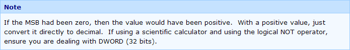
The MSB is set so we know that the above value will be negative. The next stage is to flip all the bits. This involves changing 1 to 0 and vice versa. This can be achieved quickly using the logical NOT function on a scientific calculator. You must ensure that it is set to deal with the correct number of bits.

Add 1 bit to the value above

And then convert that value back to decimal, remembering that we are dealing with a negative number:

Daylight Saving / Standard Time Start Dates
Looking at Figure 10 below, you can see two keys entitled DaylightStart and StandardStart. They hold encoded data showing the exact commencement date/time of Daylight Saving and Standard Time. To establish when daylight saving starts and ends, both keys will need to be decoded.
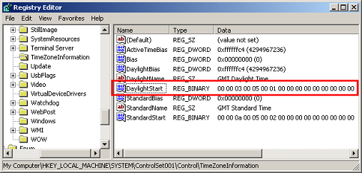
Figure 10
SYSTEMTIME Structure
This data is stored in a common structure called SYTEMTIME. This structure specifies a date and time, using individual members for the month, day, year, weekday, hour, minute, second, and millisecond.
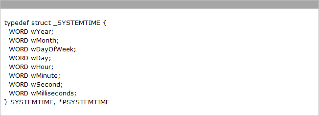
Figure 11
The data in DalylightStart is as follows:

Figure 12
Bytes 0 & 1 (0x0000 ) refer to the year from a 1900 time base. This is only required if the change is year specific and will normally be zero.
Bytes 2 & 3 (0x0003 ) refer to the month, in this case March.
Bytes 4 & 5 (0x0005) refer to the week (starts at 1 and 5 means last). In this case the last week.
Bytes 6 & 7 (0x0001) refer to the Hour. In this case it is 0100 Hours.
Bytes 8 & 9 (0x0000) refer to the Minutes. In this case it is Zero minutes.
Bytes 10 & 11 (0x0000) refer to the Seconds; in this case it is Zero seconds.
Bytes 12 & 13 (0x0000) refer to the Milliseconds, in this case it is Zero milliseconds.
Bytes 14 & 15 (0x0000) refer to the actual Day of the Week (Sunday = 0). In this case it is Sunday
For our example in Figure 12, Daylight Saving Time (DST) will start on Sunday of the Last Week in March at 0100 Hours. If we had decoded StandardStart, we would see that DST would end on Sunday of the last week of October at 0200 hours.
Links and References